Introduction
The AIY Voice Kit from Google lets you build your own natural language processor and connect it to the Google Assistant or Cloud Speech-to-Text service, allowing you to ask questions and issue voice commands to your programs. All of this fits in a handy little cardboard cube, powered by a Raspberry Pi.
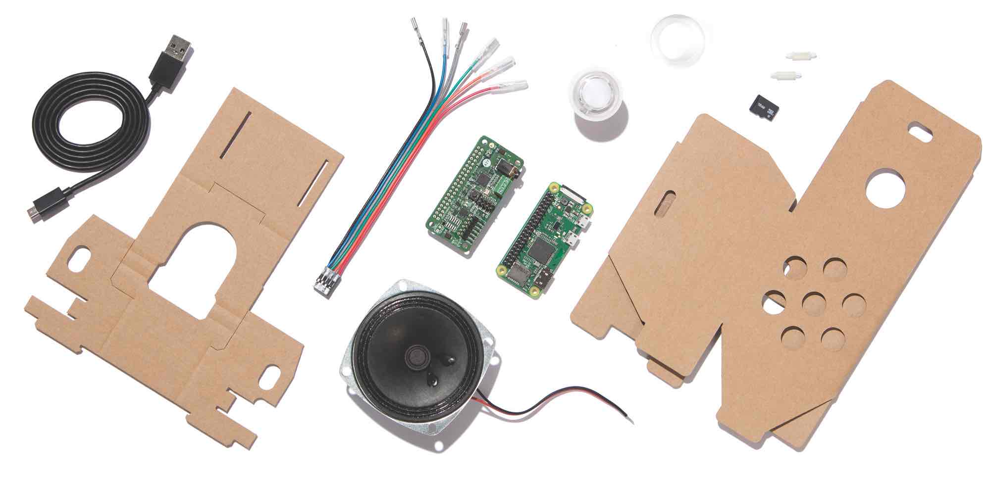
Everything you need is provided in the kit, including the Raspberry Pi.
Meet your kit
The following instructions show you how to assemble your AIY Voice Kit, connect to it, and run the Google Assistant demo, which turns your kit into a voice assistant that responds to your questions and commands.
Then you can try some other sample code or use the Google Cloud Speech-to-Text service, which converts spoken commands into text you can use to trigger actions in your code.
Time required to build: 1.5 hours
Check your kit version
These instructions are for Voice Kit 2.0. Check your kit version by looking on the back of the white box sleeve in the bottom-left corner.
If it says version 2.0, proceed ahead! If it doesn’t have a version number, follow the assembly instructions for the earlier version.
GATHER ADDITIONAL ITEMS
You’ll need some additional things, not included with your kit, to build it:
- 2mm flat screwdriver: For tightening the screw terminals
- Micro USB power supply: The best option is to use a USB Power supply that can provide 2.1 Amps of power via micro-USB B connector. The second-best choice is to use a phone charger that also provides 2.1A of power (sometimes called a fast charger). Don’t try to power your Raspberry Pi from your computer. It will not be able to provide enough power and it may corrupt the SD card, causing boot failures or other errors.
- Wi-Fi connection
Below are two different options to connect to your kit to Wi-Fi, so that you can communicate with it wirelessly.
OPTION 1: USE THE AIY PROJECTS APP
Choose this option if you have access to an Android smartphone and a separate computer.
You’ll need:
- Android smartphone
- Windows, Mac, or Linux computer
OPTION 2: USE A MONITOR, MOUSE, AND KEYBOARD
Choose this option if you don’t have access to an Android smartphone.
You’ll need:
- Windows, Mac, or Linux computer
- Mouse
- Keyboard
- Monitor or TV (any size will work) with a HDMI input
- Normal-sized HDMI cable and mini HDMI adapter
- Adapter to attach your mouse and keyboard to the kit. Below are two different options.
Adapter option A: USB On-the-go (OTG) adapter cable to convert the Raspberry Pi USB micro port to a normal-sized USB port. You can then use a keyboard/mouse combo that requires only one USB port.
Adapter option B: Micro USB Hub that provides multiple USB ports to connect to any traditional keyboard and mouse.
List of materials
IN YOUR KIT
- Voice Bonnet(×1)
- Raspberry Pi Zero WH(×1)
- Speaker(×1)
- Micro SD card(×1)
- Push button(×1)
- Button nut(×1)
- Button harness(×1)
- Standoffs(×2)
- Micro USB cable(×1)
- Speaker box cardboard(×1)
- Internal frame cardboard(×1)
FOLD THE INTERNAL FRAME
Orient the frame
Let’s start by folding the internal frame, which will hold the electrical hardware inside the box.
Lay the frame on the table in front of you like the photo. The left slit should be closer to the cardboard edge. 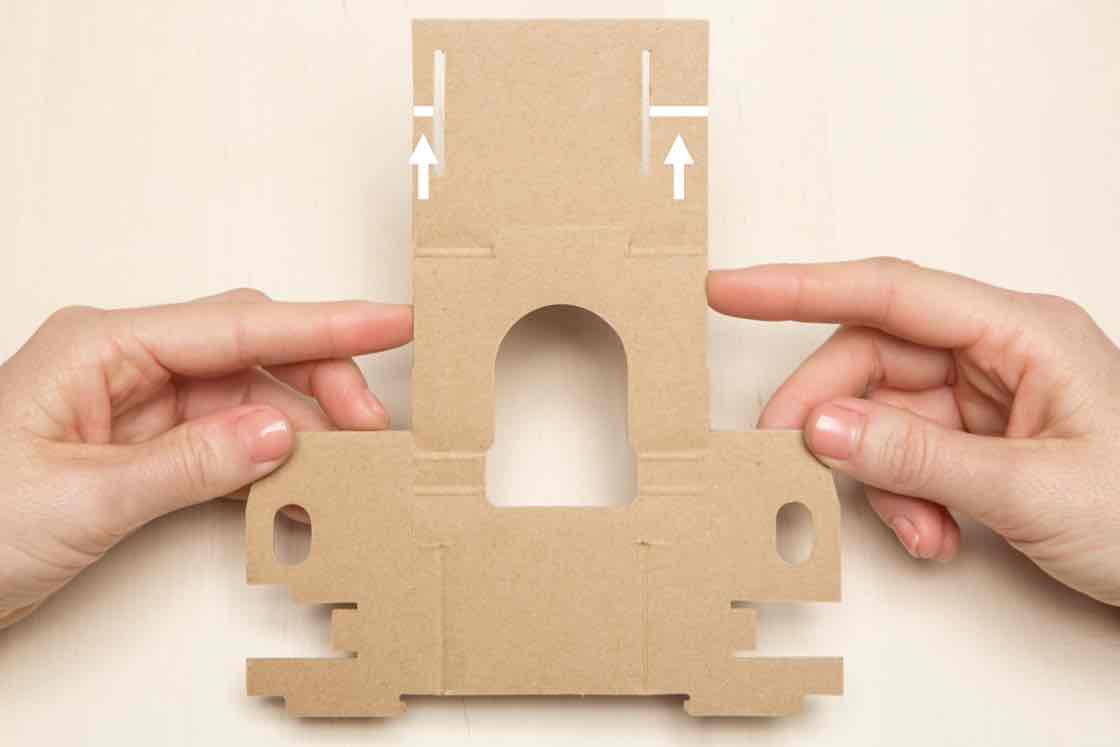
Fold long flap
Fold the long flap away from you and downwards along the two creases.
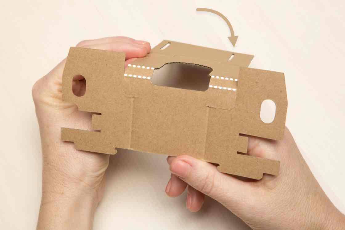
Fold left and right flaps
Fold the two highlighted flaps toward you.
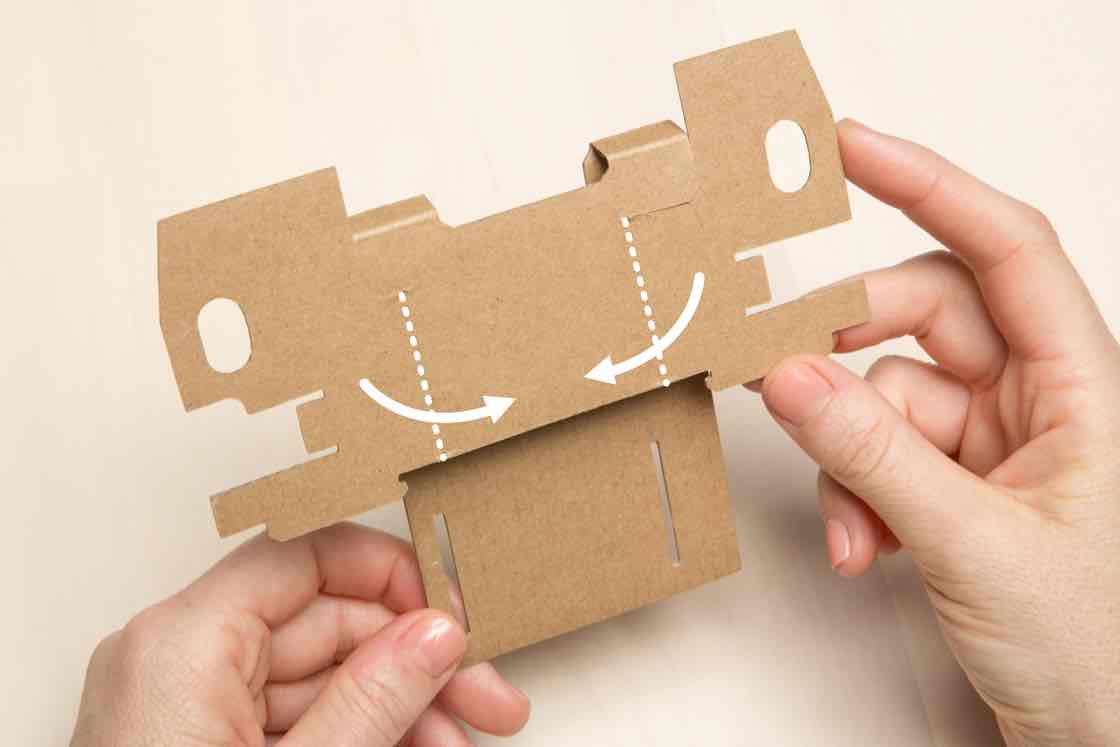
Fold the bottom flap
Fold the bottom flap upward toward you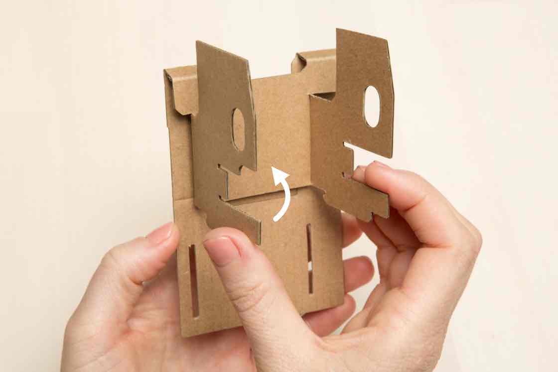
Align the bottom
The slits on the bottom flap will align with two notches.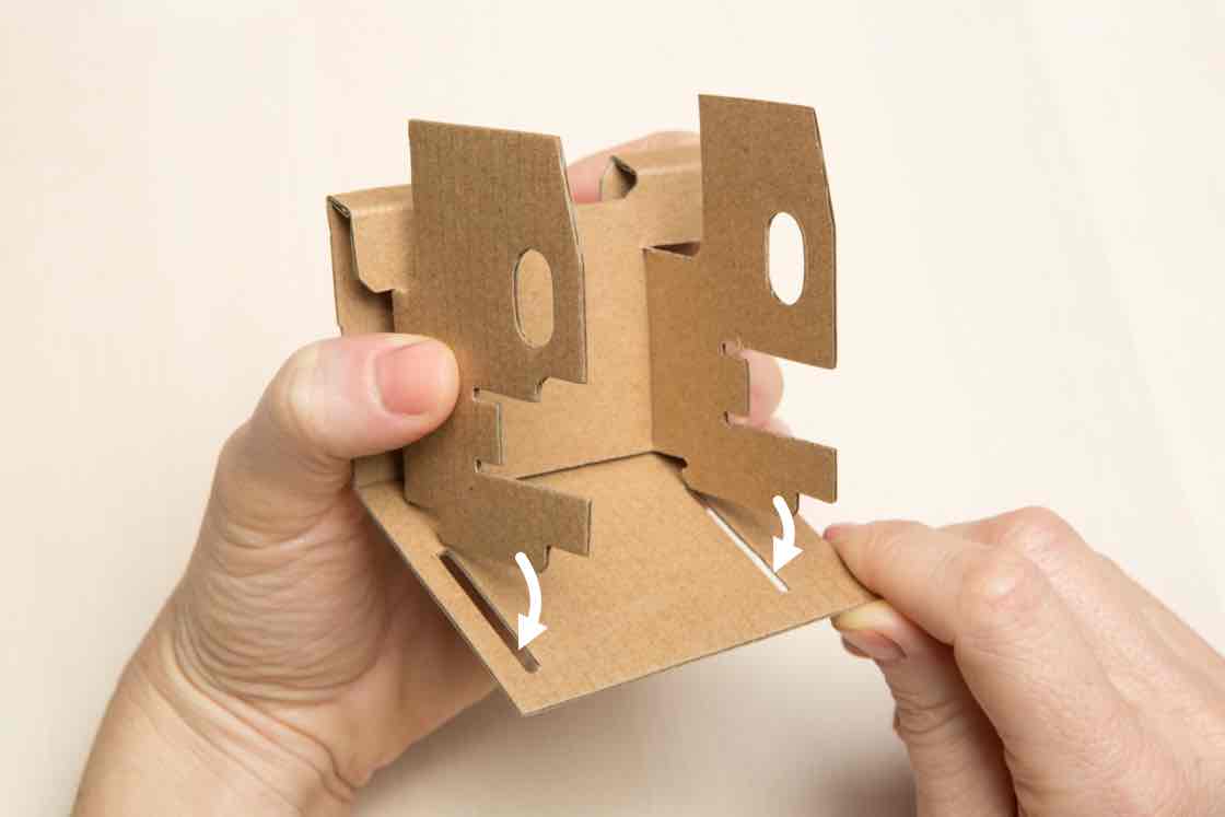
Insert the notches
Insert the notches into the slits.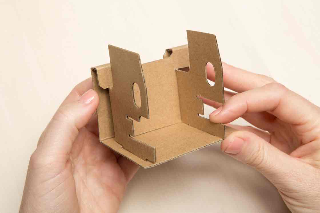
Check frame alignment
Look at the bottom of your frame. The slit closer to the edge should be on the left.
If yours looks different, you probably folded the frame the wrong way. Unfold it and check step 1 in fold the internal frame.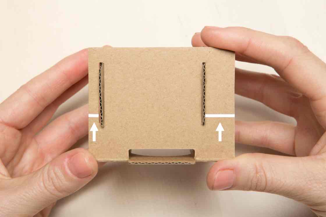
Set the frame aside
The internal frame is built. Set it aside for now; we’ll need in the next phase.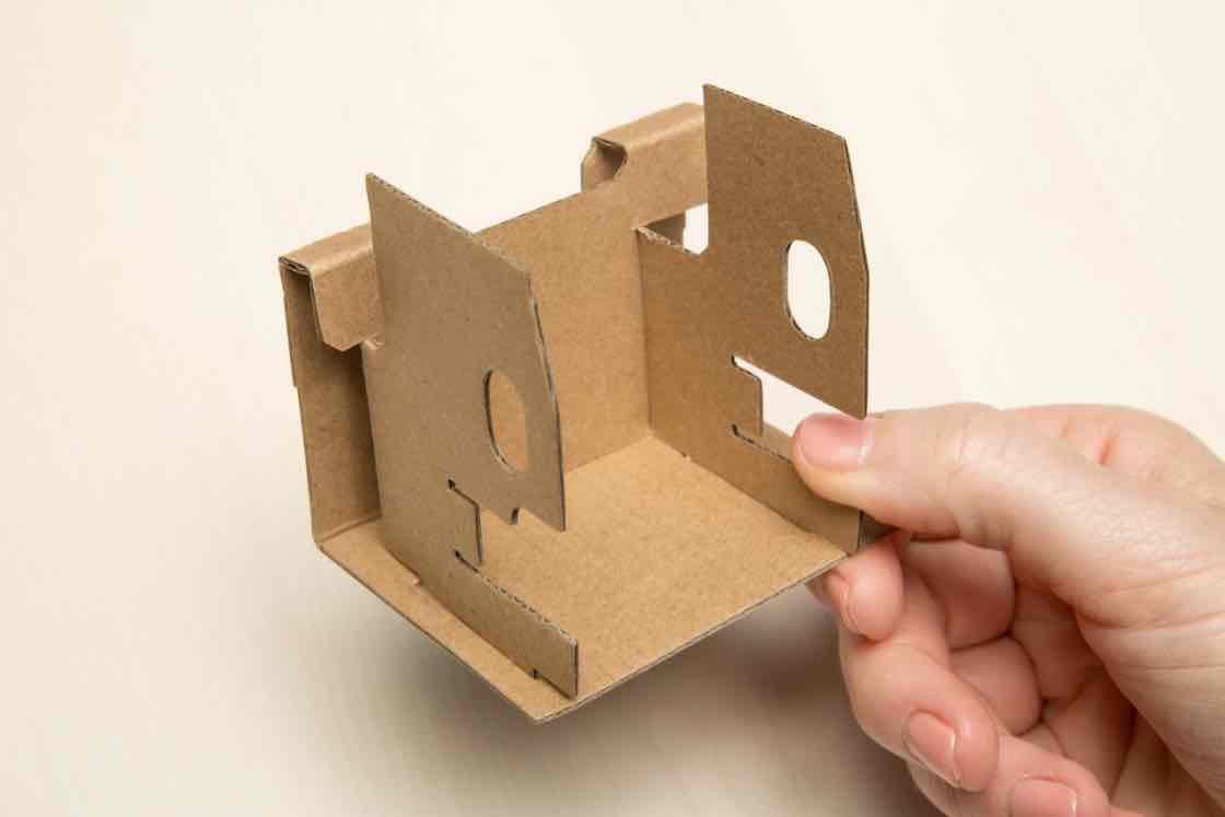
CONNECT THE BOARDS
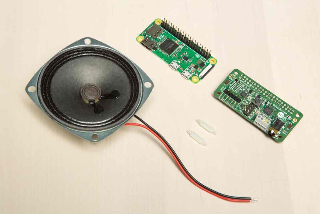
Gather your boards and speaker
Now it’s time to connect all the electrical hardware together. Gather your:
- Raspberry Pi
- Voice Bonnet board
- Standoffs (x2)
- Speaker
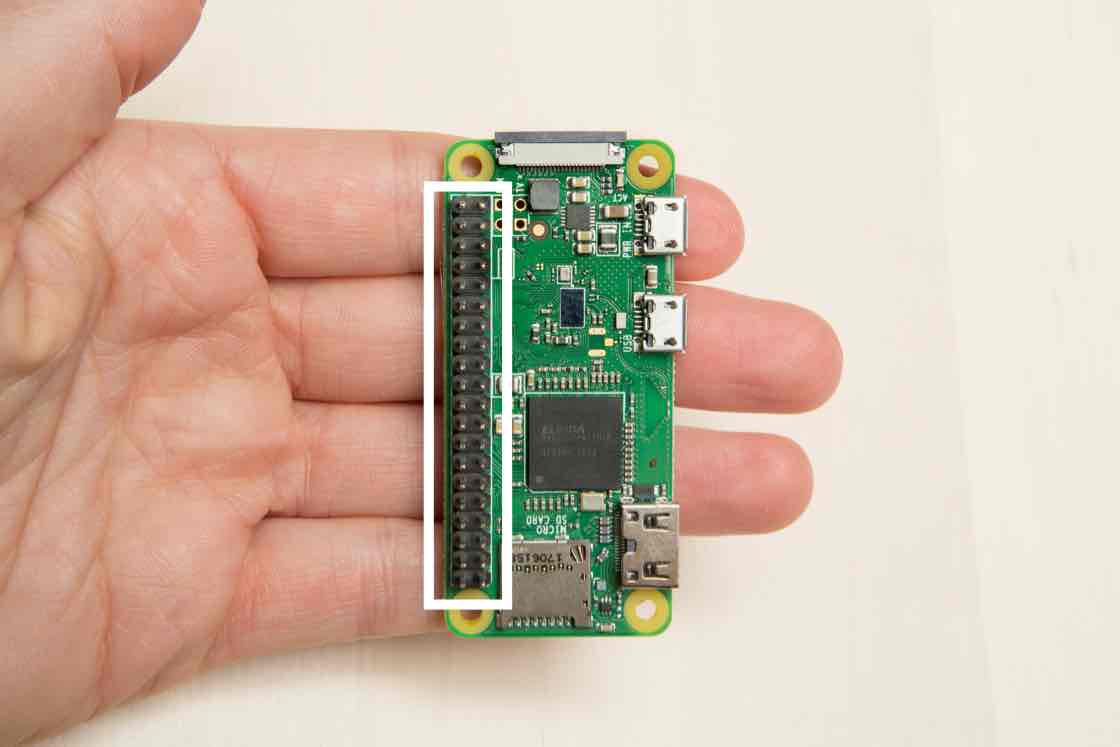
Orient your Raspberry Pi
Find your the Raspberry Pi board and orient it so that the 40-pin header is on the left edge of the board, like the photo.
- WARNING: First make sure your Raspberry Pi is disconnected from any power source and other components. Failure to do so may result in electric shock, serious injury, death, fire or damage to your board or other components and equipment.
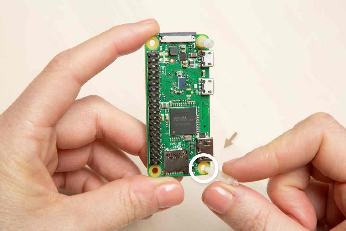
Insert standoffs
Holding the board in your hand, insert the standoffs into the holes on the right edge of the board, opposite the header.
It will take a firm push to get the standoffs to click in, so you should support the board from underneath so it doesn’t bend too much.
It’s always best to hold the board by the edges (not by the top and bottom surfaces).
Connect the boards
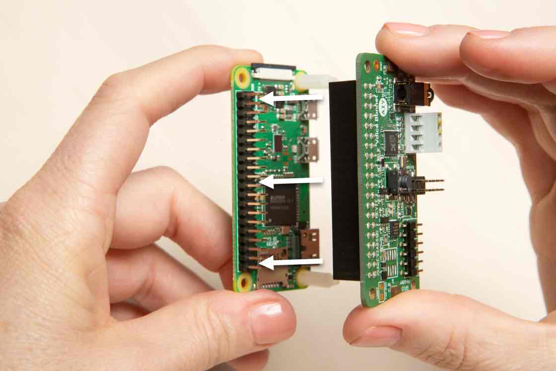
Grab your Voice Bonnet board. It has a header connector on the bottom of the board.
Align the header connector with the pin header on the Raspberry Pi, then press down to connect the headers. Firmly push on the other side of the Voice Bonnet to snap the standoffs into place. Push near the standoffs, not in the center of the board.
Check connections
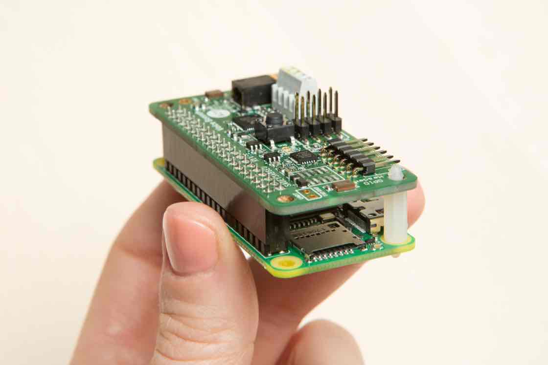
Make sure the standoffs have snapped into the boards and that the 40-pin header is pushed all the way down so that there is no gap between the two boards.
WARNING: Failure to securely seat the Voice Bonnet may cause electric shock, short, or start a fire, and lead to serious injury, death, or damage to property.
Loosen screws
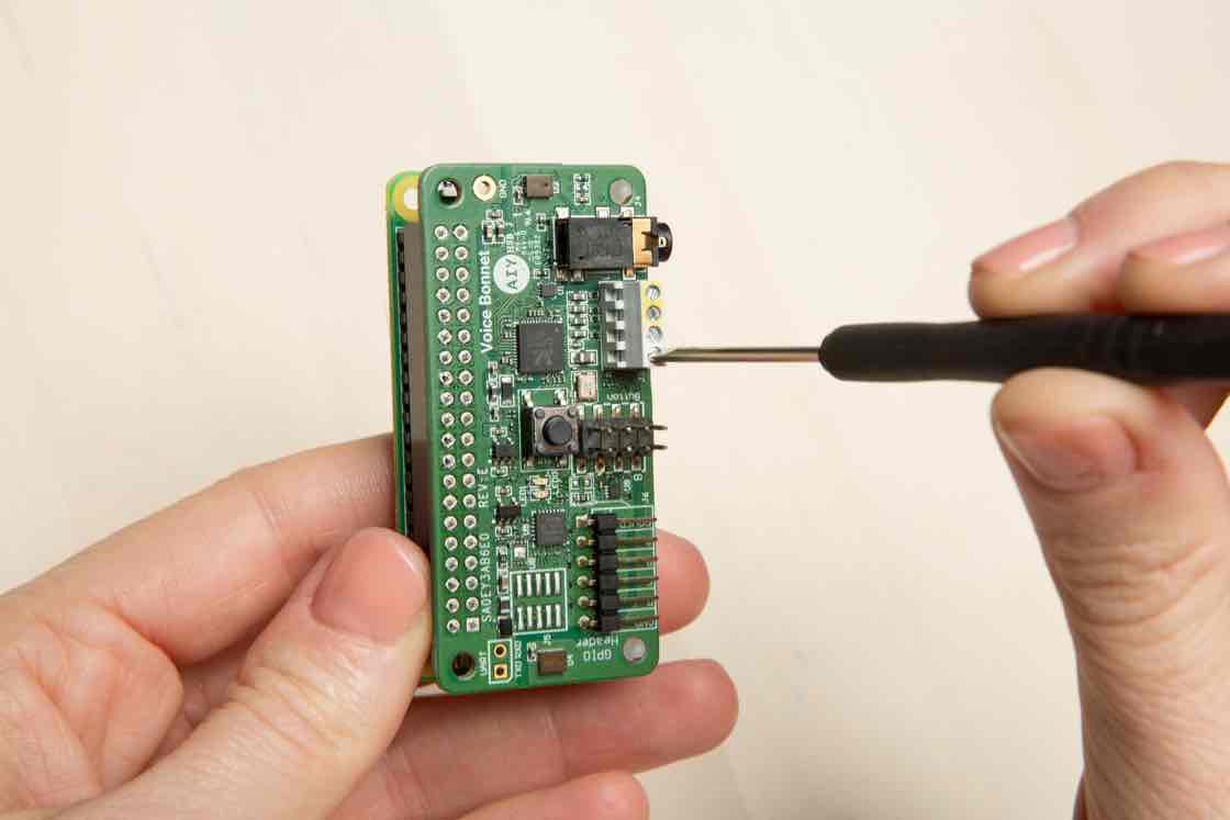
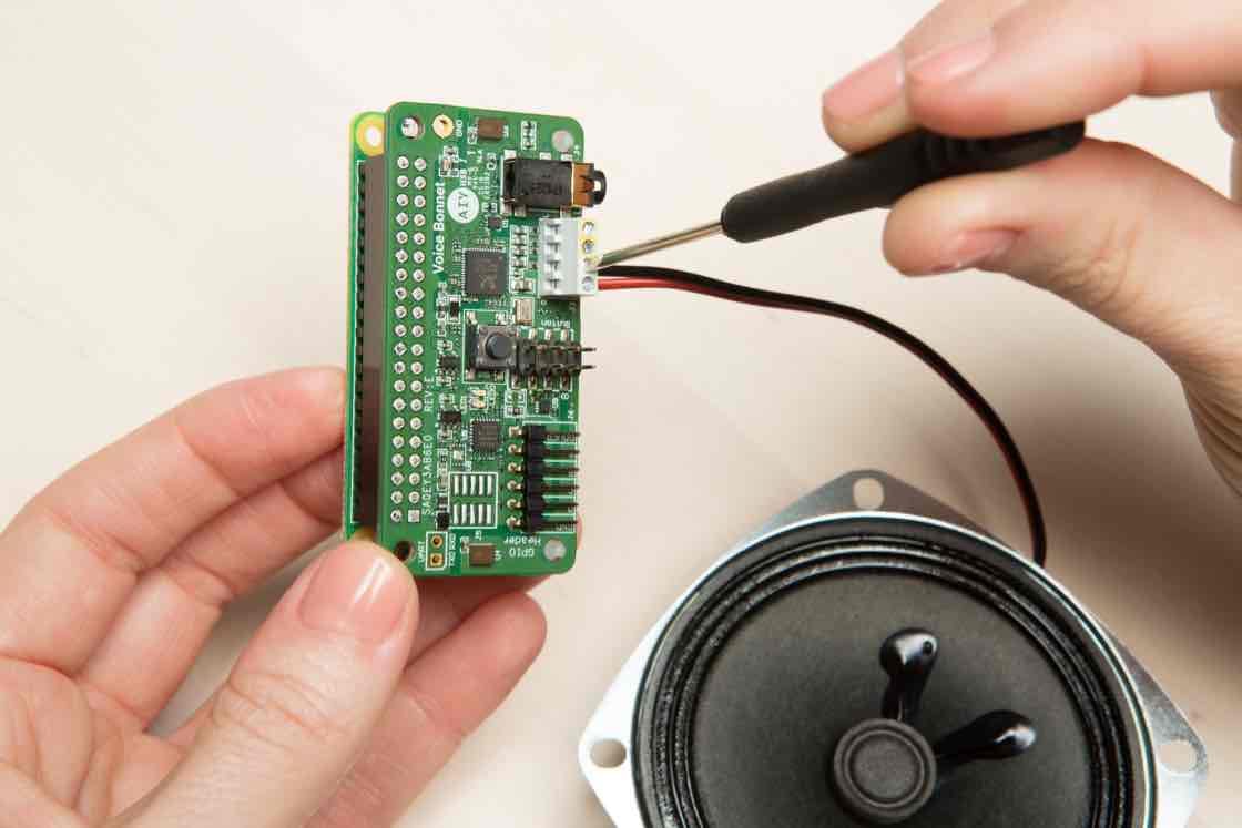
Grab your 2mm screwdriver and loosen the two bottom screws of the screw terminal so that you can insert the speaker wires.
Insert speaker wires
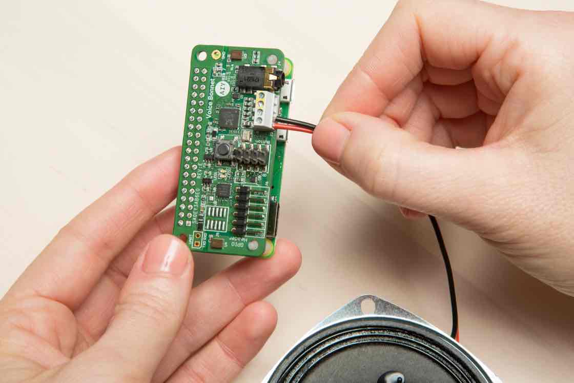
Take your speaker and find the red and black wires attached to it. Insert the red wire into the bottom slot of the left-most terminal and gently push it in as far as you can. Do the same for the black wire in the second terminal from the left.
What are the speaker wires for? The red and black wires transmit electrical signals which are converted to sound by the speaker.
Secure wires
Secure the wires by using your 2mm screwdriver to turn the screws clockwise.
WARNING: Failure to secure the wires or leaving wires exposed may cause electric shock, short, or start a fire, and lead to serious injury, death, or damage to property.
Add boards to the frame
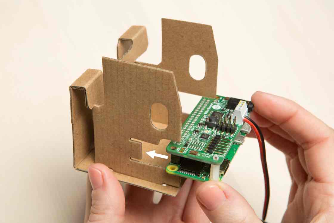
Now that your speaker is connected to the terminals, we can put the boards into the internal frame.
Slide the boards into the internal frame you folded earlier. The board slides into a slot that looks like a mouth 😮
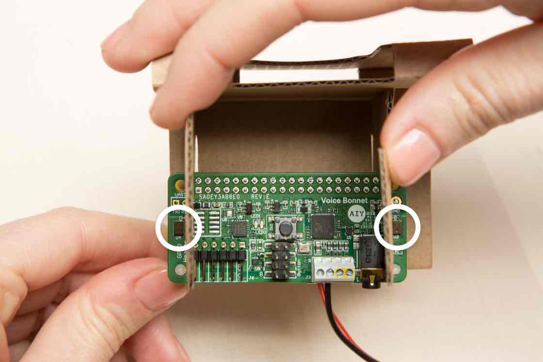
Check board alignment
The microphones on the left and right edges of the board (circled in white) should be outside the internal frame.
Insert speaker
Slide the speaker down into the internal frame.
WARNING: The speaker contains magnets and should be kept out of reach of children and may interfere with medical implants and pacemakers.
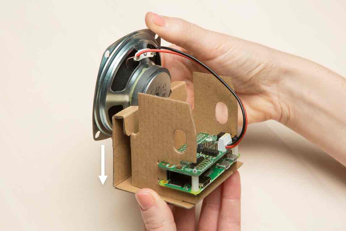
Check that the speaker is secure
Make sure the speaker is snug and secure.
Now that your electrical hardware is secure on the cardboard frame, let’s build the box it goes into.
PUT IT ALL IN THE BOX
Open the speaker box
Find the speaker box cardboard and pop it open by squeezing along the edges of the box.
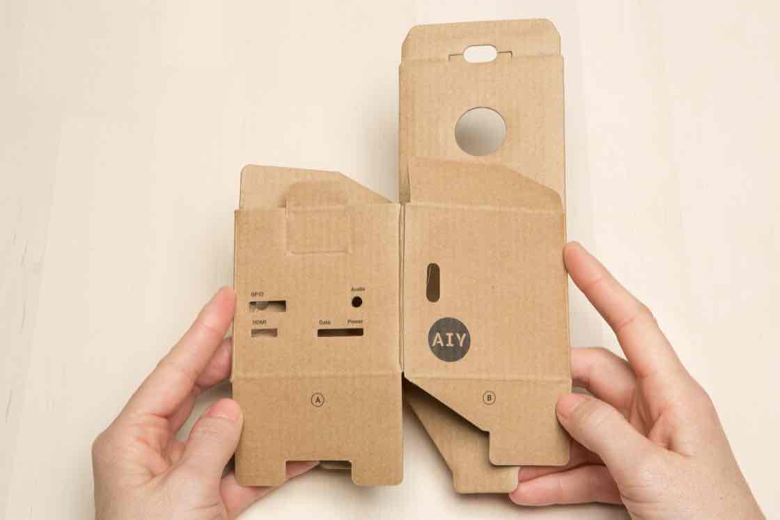
Fold flap A
Fold flap A down into the box.
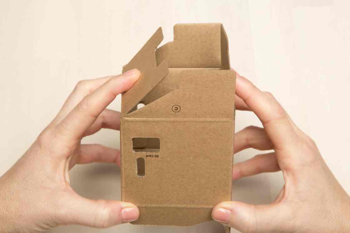
Fold flaps B and C
Then fold flaps B and C down into the box.
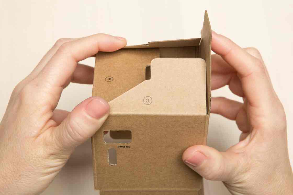
Fold flap D
Lastly, fold flap D down, pressing until it locks into place.
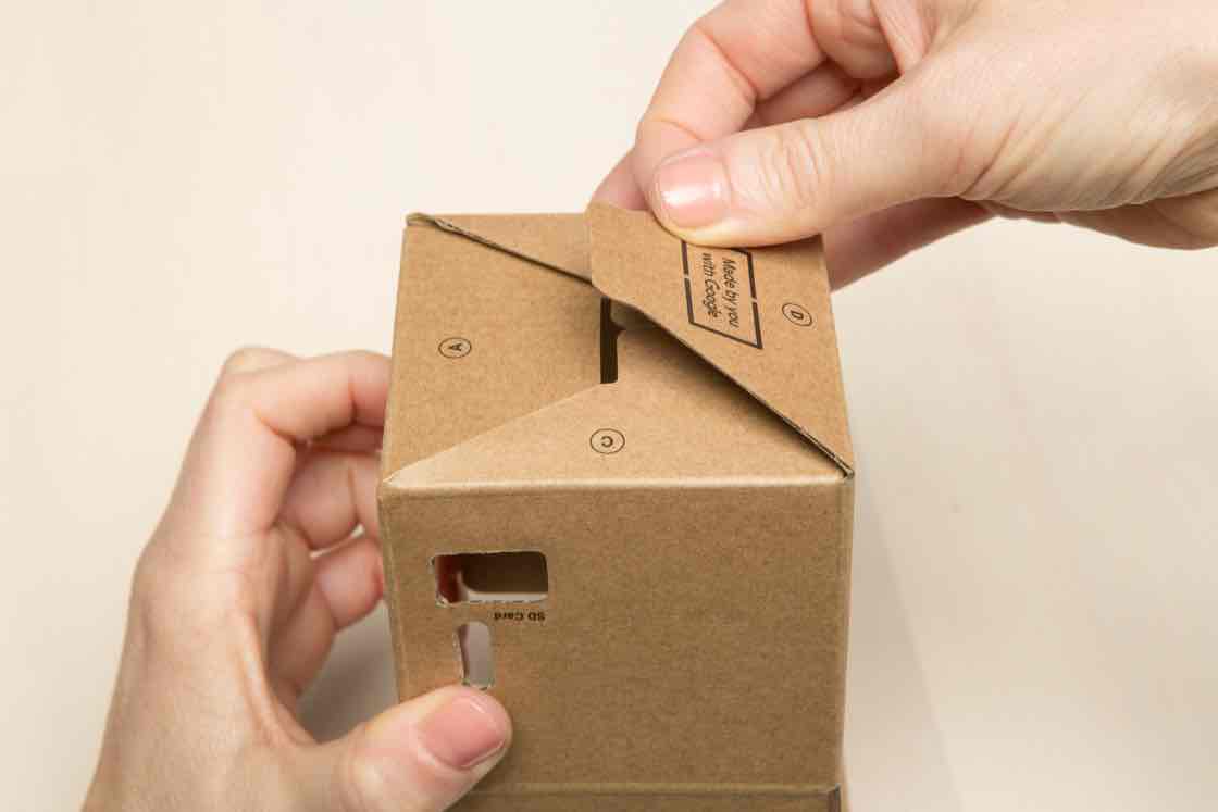
Check the box bottom
The bottom should be secure. In the next step we’ll bring it all together.
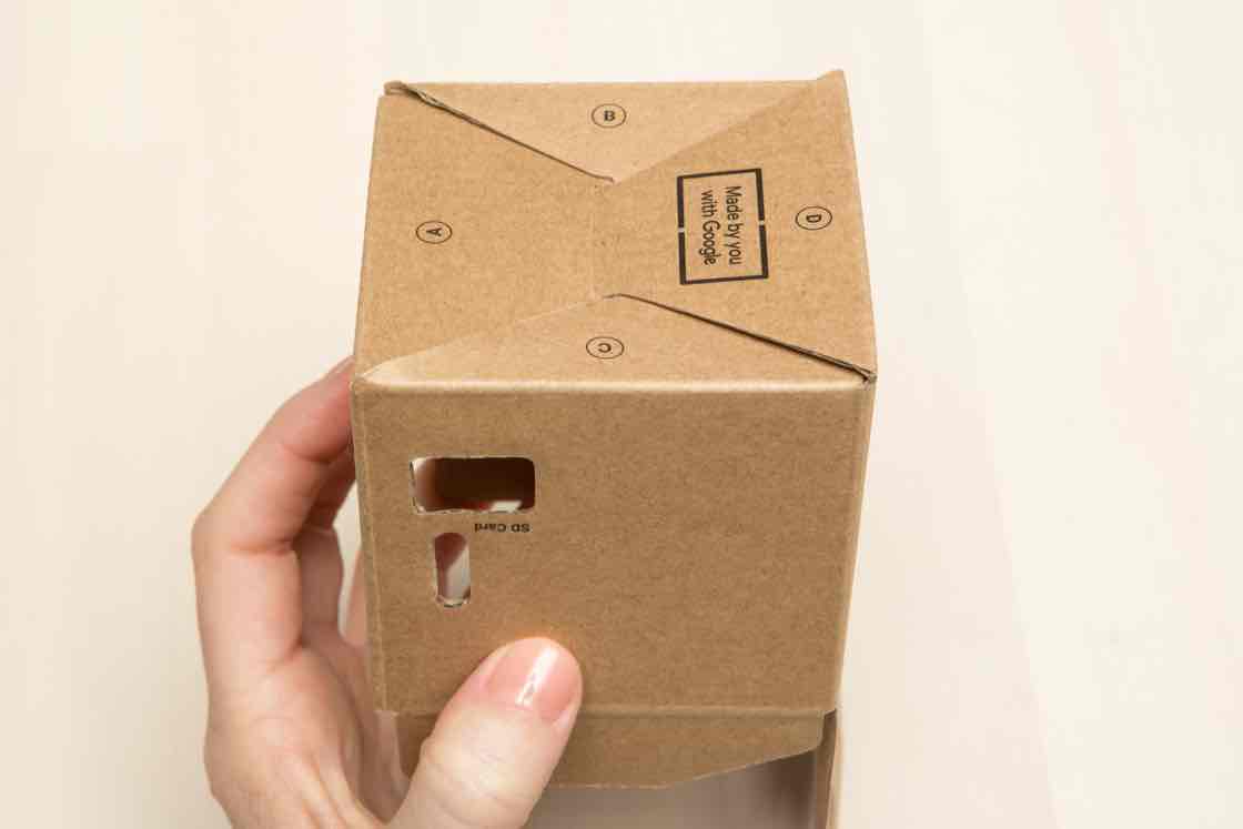
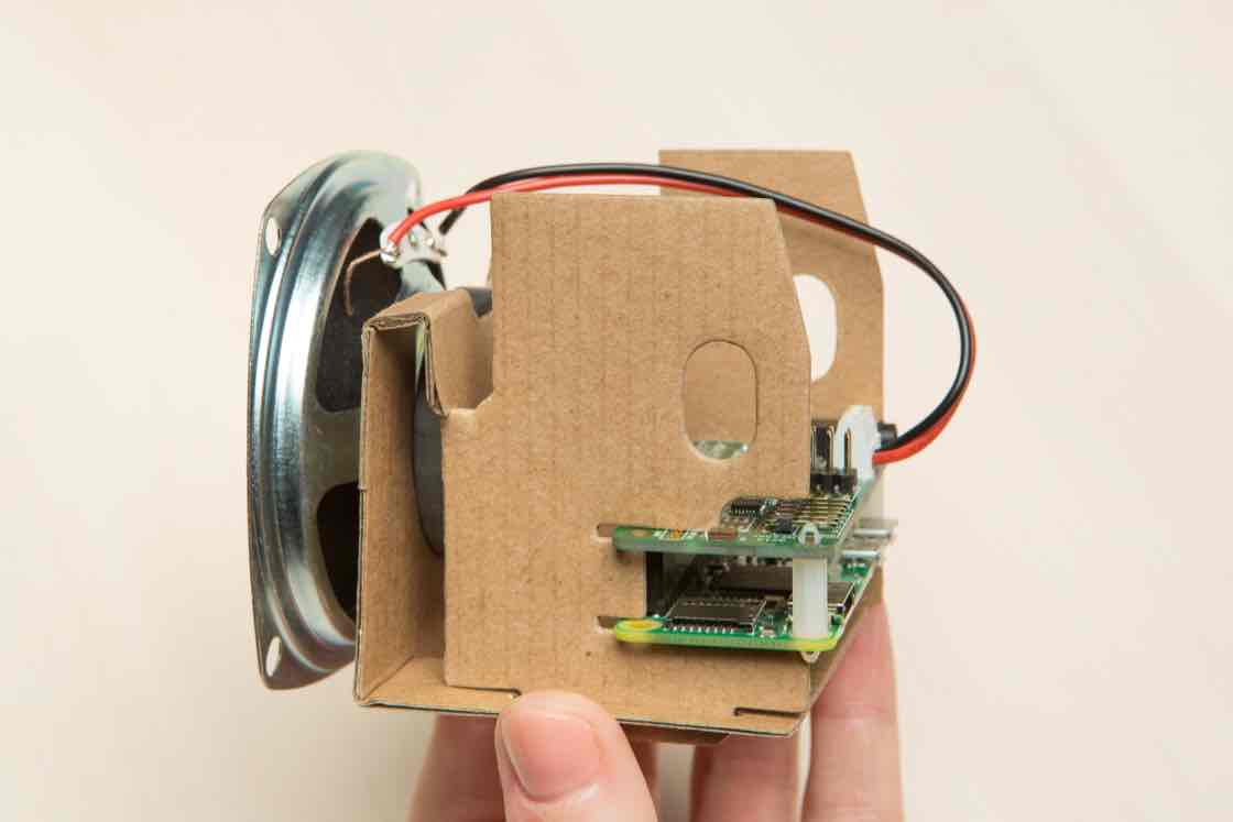
Slide the internal frame inside
Slide the internal frame into the speaker box. Make sure the speaker is lined up with the side of the cardboard box that has circular holes.
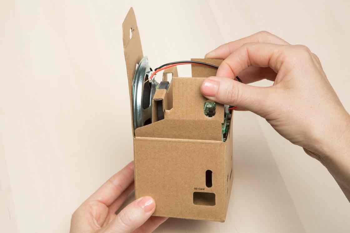
Check alignment of internal frame
Once it’s in, check the sides of the internal frame. There should be more space between the internal frame and the right side of the speaker box.
Yours looks different? If the inside of your box looks different, you might need to fold the internal frame the other way. Check step 7 in fold the internal frame for more help.
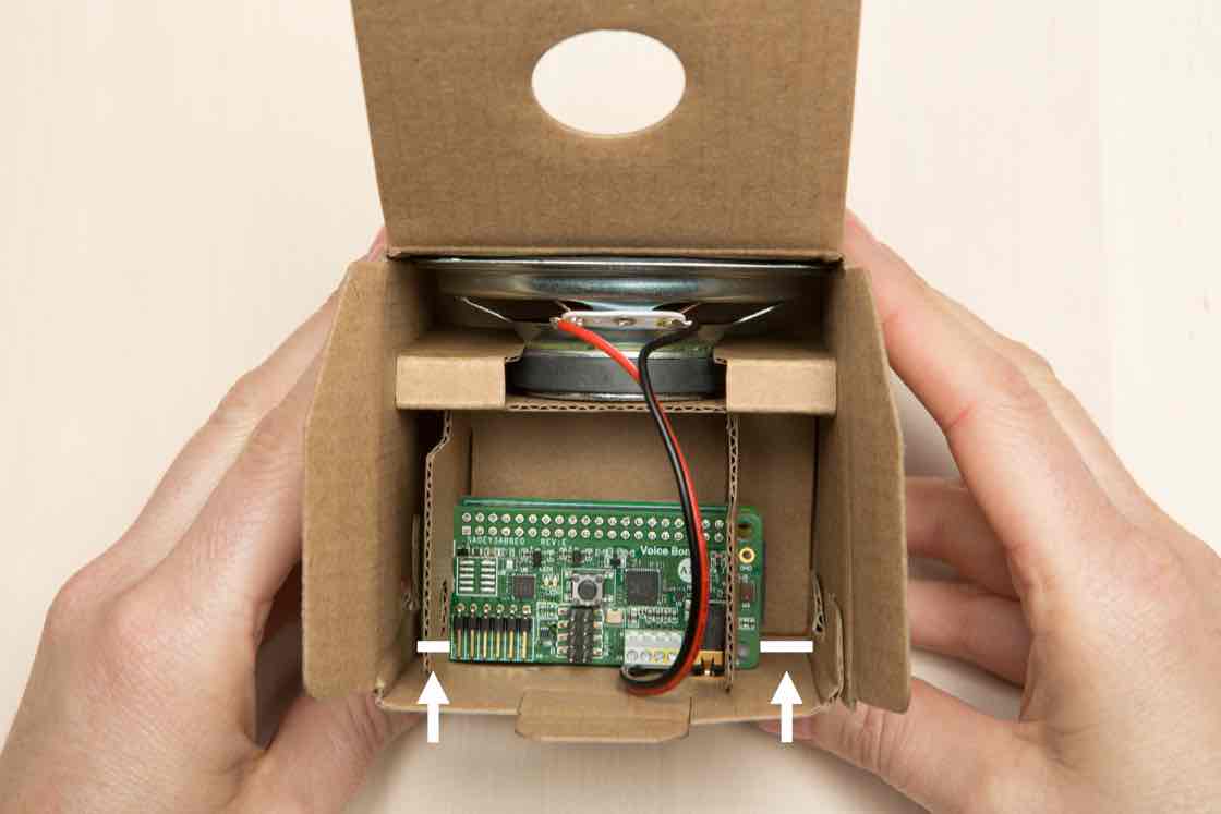
Check connectors
Make sure the connectors are lined up with the cardboard cutouts. The connectors are used to plug in things like your SD card and power.
WARNING: Forcing connectors into misaligned ports may result in loose or detached connectors. Loose wires in the box can cause electric shock, shorts, or start a fire, which can lead to serious injury, death or damage to property.
Yours looks different? If your connectors don’t line up, you may have inserted the internal frame the wrong way. Check step 26 in put it all in the box for more help.
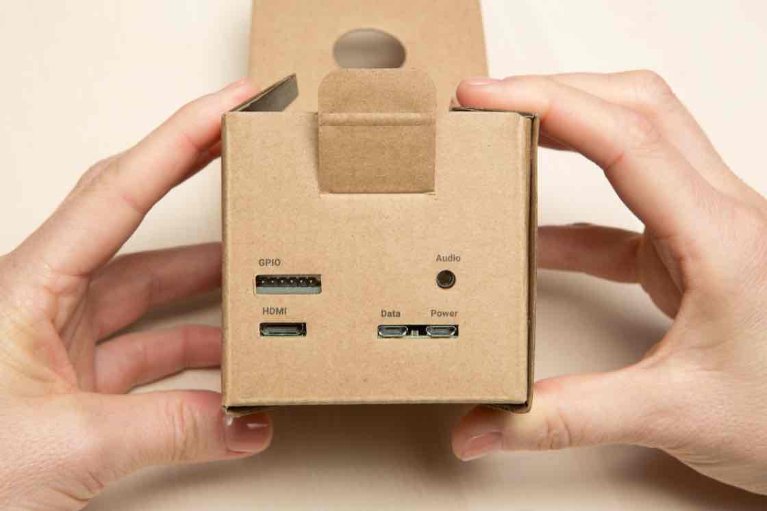
ADD THE BUTTON
Gather your pieces
It’s time to add the button. From your kit, round up the:
- Push button
- Button nut
- Button harness

Insert the push button
Insert the push button into the hole on the top of your cardboard box.
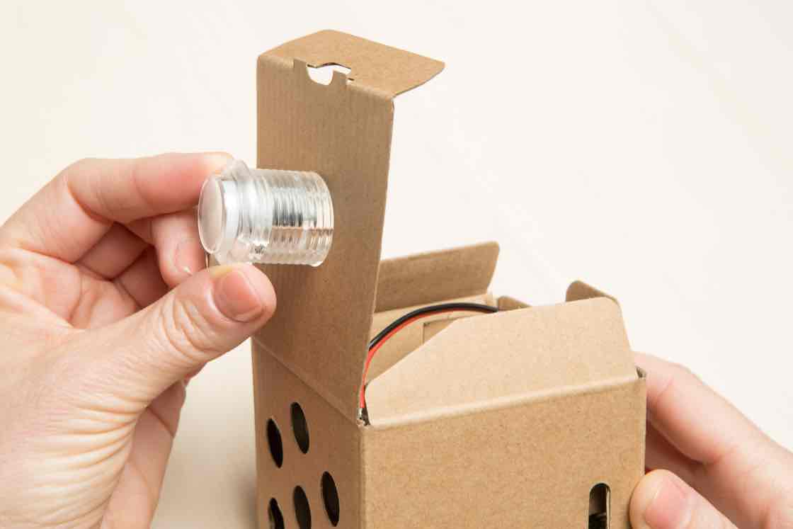
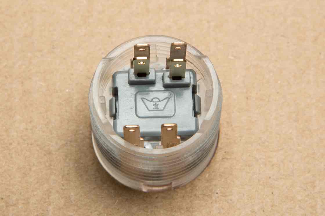
Orient the button
On the other side, orient the button so that the side with four prongs is on the top (check the photo).
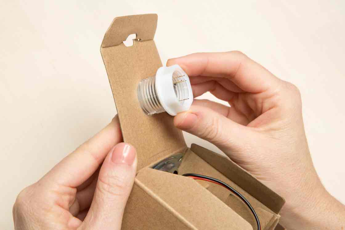
Screw on the button nut
Screw on the button nut to secure the button in place.
Make sure the wider, flanged side of the nut is facing the cardboard flap.
Make sure your button is still oriented so the four prongs are on top.
Plug in your wires
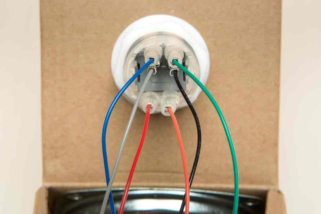
Now it’s time to plug in the wires on the button harness. Take the button harness and find the end with six individually colored wires.
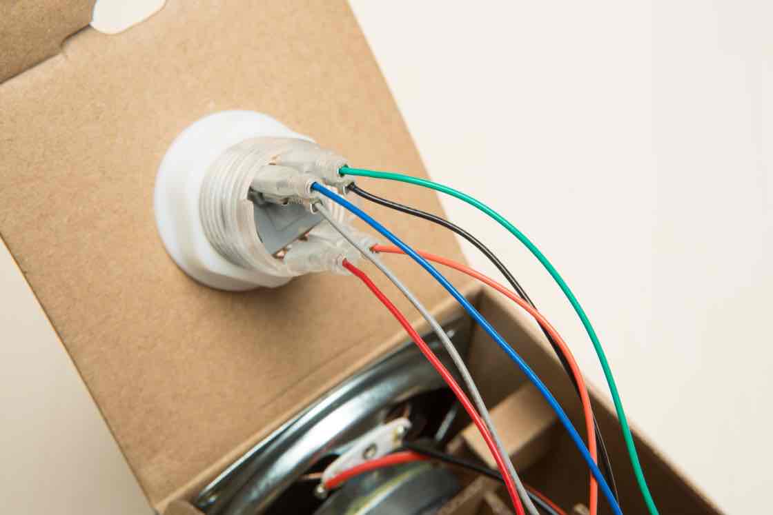
Plug each of those wires in the correct slot by matching its color to the image.
- Top row: blue and green
- Middle row: grey and black
- Bottom row: red and orange
Check wires
Double-check to make sure your wires are plugged in the same way as the image.
Find the 8-pin connector on the Voice Bonnet
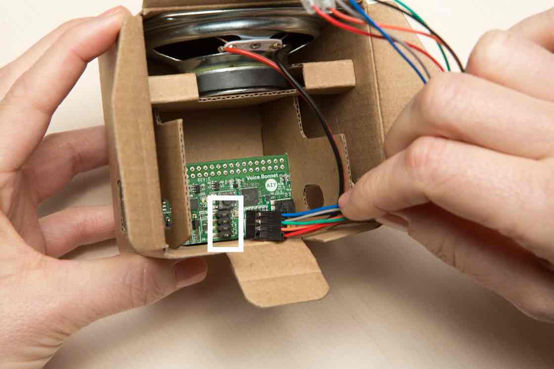
To plug in the button harness, first find the 8-pin connector on your Voice Bonnet board, outlined in a white rectangle in the photo.
With the speaker facing away from you, plug the black wire into the top-right slot. Plug the blue wire into the top-left slot. Double check to make sure this is correct.
WARNING: Failure to securely seat the connector may cause electric shock, short, or start a fire, and lead to serious injury, death, or damage to property.
Fold the top flaps
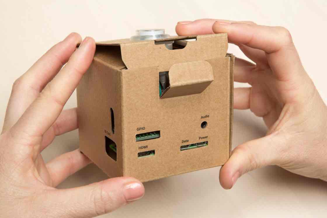
Close your box by folding down the top flaps.

Tuck in the tab
Secure the box by tucking in the tab.
Insert the SD card
The SD card is pre-loaded with all the software you need.
With the arrow side facing up, insert your SD card into the silver slot on the Raspberry Pi, which you can find through the cardboard cutout labeled SD Card.
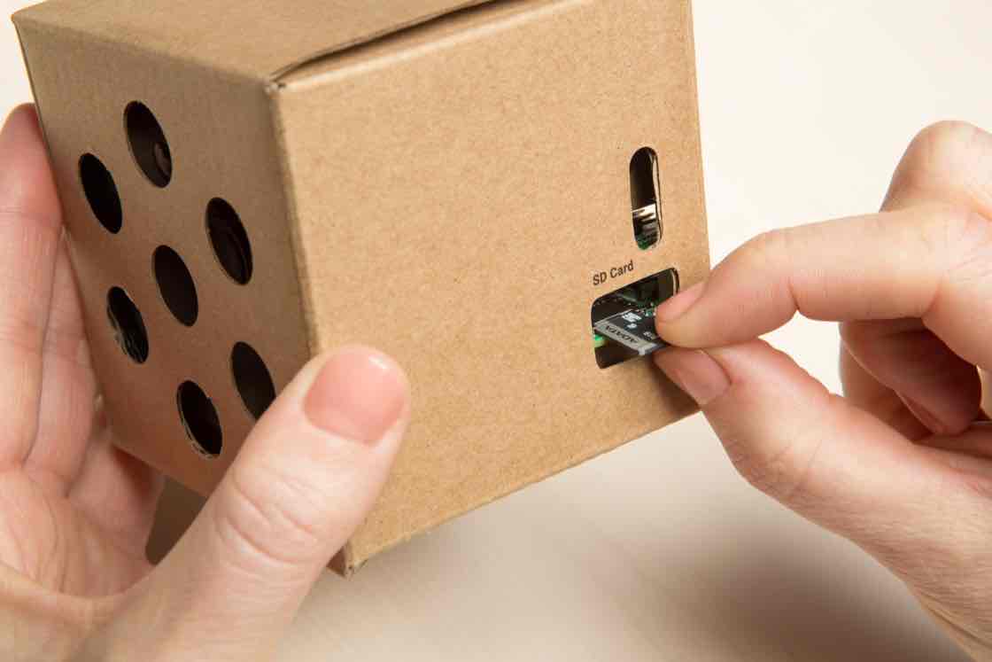
Congrats, you’ve just assembled the Voice Kit hardware!
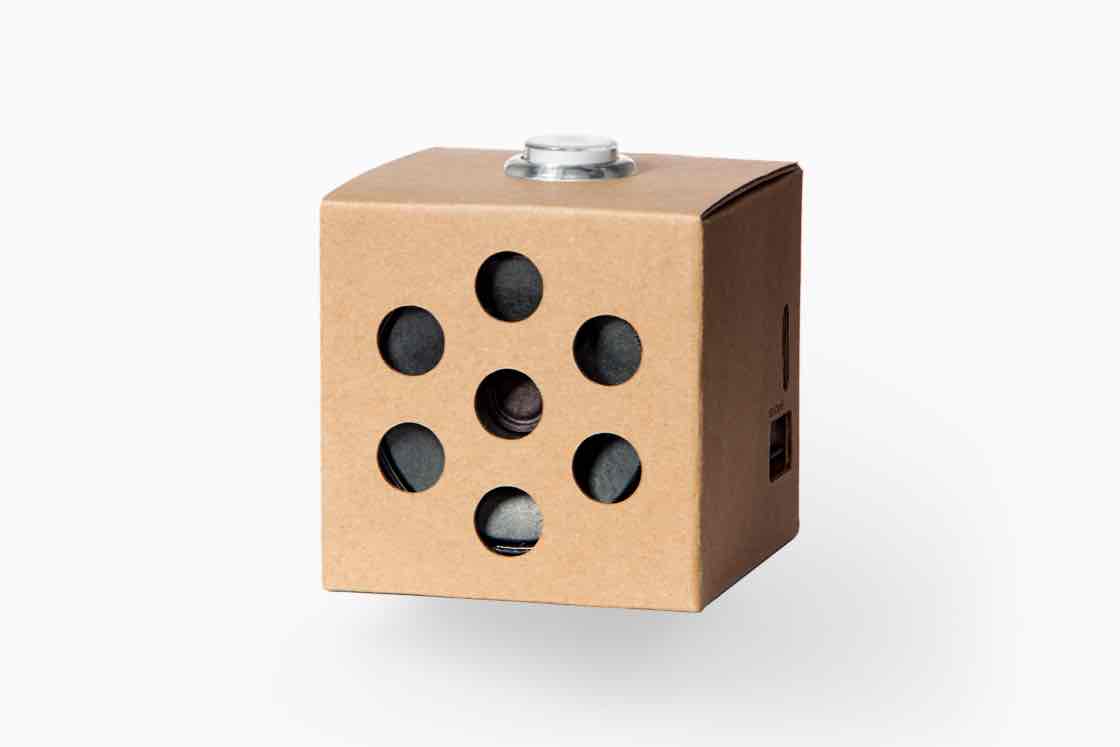
Now you’re ready to connect your kit to the Google Assistant.
This article has been published from the source link without modifications to the text. Only the headline has been changed.


